In a previous post I have discussed the rather confusing layout of the Arduino robot board. After a comment by Harri Laitinen (thanks!) I have realised I had left behind some important details about the naming and organisation. So here it is. As mentioned there are analog (TK*) and digital pins (TKD*). Confusingly they are interleaved.
For example if you look at TK2, there are analog pins on the white plastic support, but behind it you will find a mixture of analog (S2 and S2.1) and digital ones (TK1s and US1 and US1.1). This is already confusing but the way the 5V and ground are laid out is even more confusing.
Here is what I understood so far.
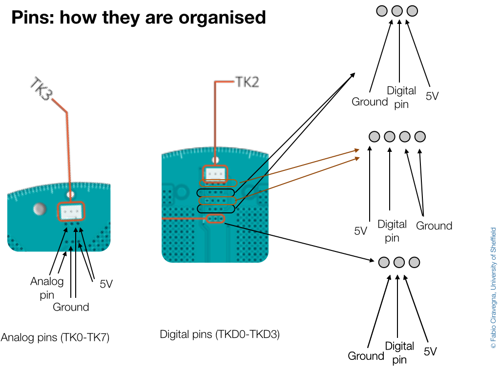
That does not look like the most intuitive way to organise them but there you are.
As for the naming of the different groups of pins, I have found that the south digital pin is equivalent to TKD5.
As for the naming of the different groups of pins, I have found that the south digital pin is equivalent to TKD5.
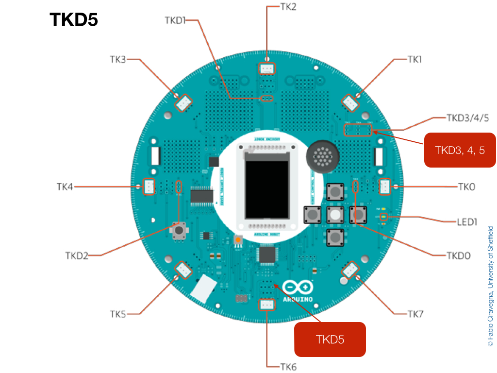
If anyone out there cared to check it would be great. Thanks!
 RSS Feed
