(please note: you may also be interested in further details about the board given in a following post)
Since I have got my Robot on Christmas day I have been trying to figure out the board layout organisation. I am not an expert in electronics (well I know how to use a computer) and I may have missed some important information on the web, but I could not find anywhere an explanation on how to use the different pins.
So I have tried to work it out myself. As said I am not an expert and I may have made some serious mistakes. Anyway here it is the result of my thinking. Please let me know if you find any mistake.
What is what?
Well, that was the first hurdle. Yes there is information on the Arduino Robot official page but I think it is rather limited. They also provide the schematics but I had problems in getting the two together. It must be because I am not an expert I am sure, but others can have the same issue, so here it is.
First and foremost here is the general organisation:
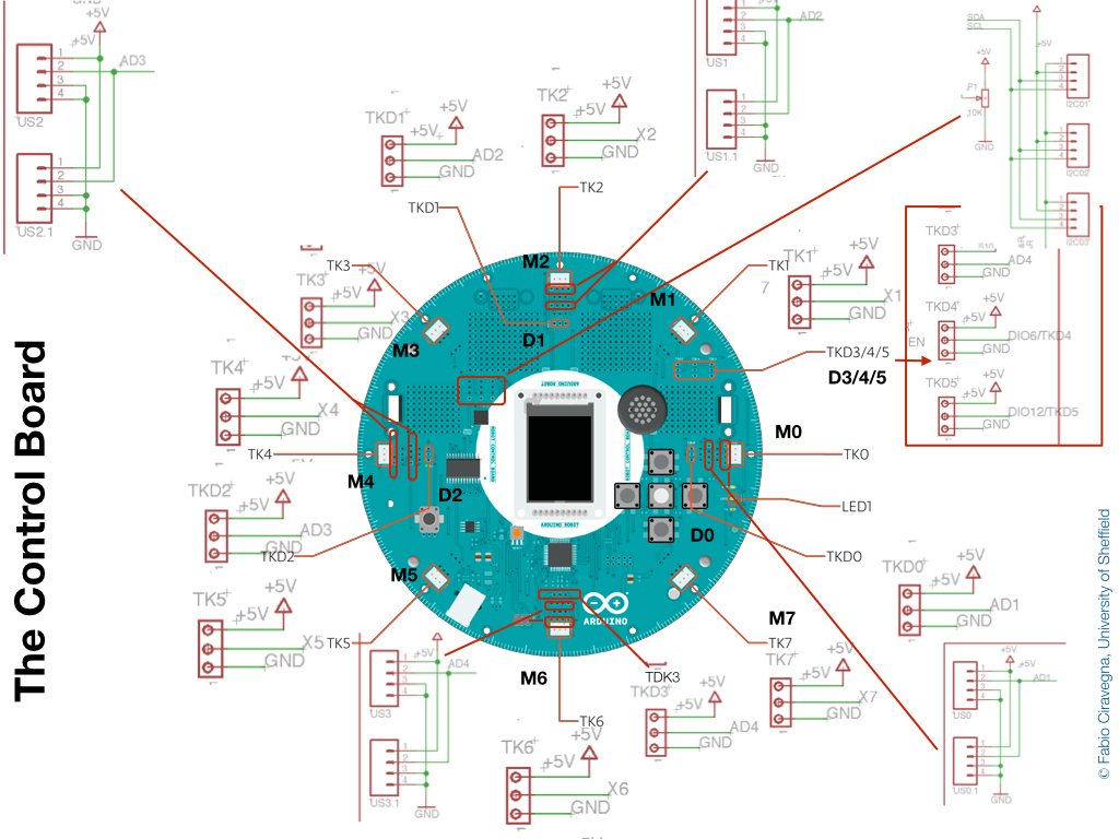
I created this by composing the official board figure found on the Arduino Robot page with parts of the schematics found on the same page. The image above is not complete. There are some parts missing that can be found in the next images. I could not fit everything there.
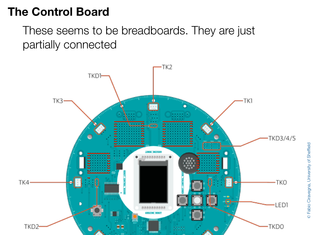
Let's see the details of the front of the board:
Let's see the details of the front of the board:
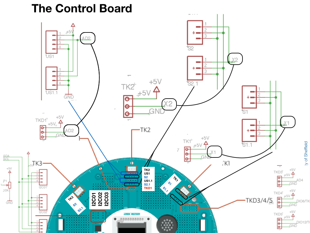
As you see there are lots of holes (which I suppose can still be called pins) that are not documented on the official page. The plastic Tinker connector called TK2 (confusingly called M2 on my board) is analog and works on channel X2 (I hope it is called a channel!). This is the same channel where S1 and S2.1 work. I cannot fathom why they did use different numbers.
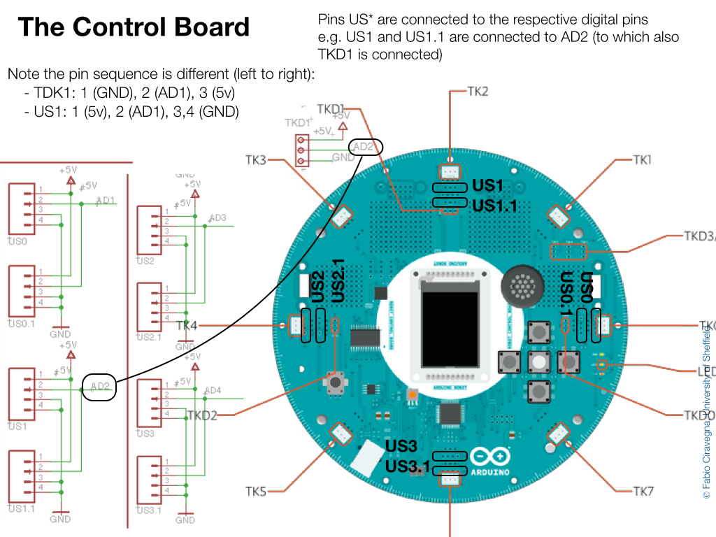
TK0..TK7 are all analog pins. They can be written with Robot.analogWrite() and read with Robot.analogRead(). However, they can be also read as digital using Robot.digitalRead() (see http://arduino.cc/en/Reference/RobotDigitalRead)
Instead, TKD0..TKD3 are digital pins and can be read and written using Robot.digitalRead() and Robot.digitalWrite().
There are other positions (called USx and USx.y) that are digital and work on the same channel of TKDz. So, for example, US1 and US1.1 work on channel AD2 which is shared by TKD1. There are a number of these USx pins.
Equally there are a number of Sx pins that are analog and connected to the TKz pins.
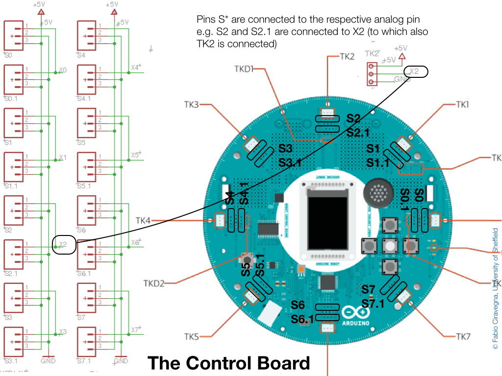
For example S2 and S2.1 work on X2 like TK2.
The last part I was wondering were the set of ordered holes that look pretty much like breadboards. Indeed they look like partially connected breadboards. These are the connections I could work out. I found them by looking at the signs on the board and verifying using a LED connected to a digital pin.
The last part I was wondering were the set of ordered holes that look pretty much like breadboards. Indeed they look like partially connected breadboards. These are the connections I could work out. I found them by looking at the signs on the board and verifying using a LED connected to a digital pin.
Well, that is what I was able to work out. Please feel free to leave comments. And especially to point out errors.
 RSS Feed
